We remain fully operational. Our teams are working around the clock to ensure your deliveries continue safely.

قم بتنزيل التطبيق


معلومات عنا
حقوق الطبع والنشر © 2024 Desertcart Holdings Limited
قم بتنزيل التطبيق
📡 Unlock the power of ultra-sensitive signal detection — don’t let weak signals hold you back!
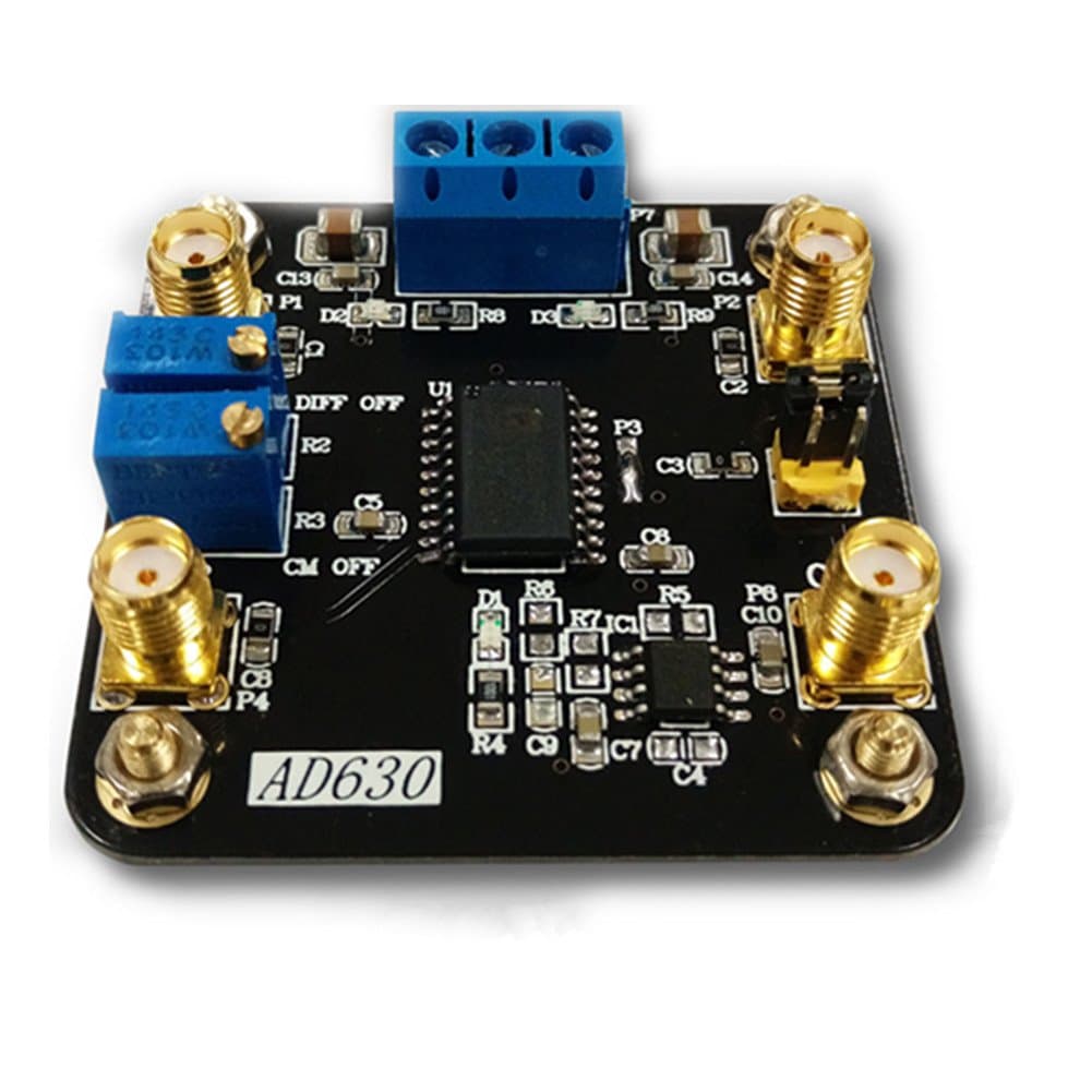
The Taidacent AD630 is a compact 2-channel balanced modulator/demodulator amplifier module engineered for weak signal detection. It boasts a remarkable 100 dB noise recovery capability, a swift 45 V/μs slew rate, and ultra-low -120 dB crosstalk, making it ideal for precision RF applications. With pin-programmable gain and a configurable low-pass filter, this module offers professional-grade performance in a small footprint.

| ASIN | B07CXM2VQ7 |
| Best Sellers Rank | #95,865 in Electronics ( See Top 100 in Electronics ) #29 in RF Modulators |
| Date First Available | May 6, 2018 |
| Is Discontinued By Manufacturer | No |
| Item Weight | 0.81 ounces |
| Item model number | AD630 |
| Manufacturer | Taida |
| Package Dimensions | 2.5 x 2.4 x 0.7 inches |
F**D
Not what it's supposed to be
The board is pretty solidly built, but doesn't come close to the one on the instruction sheet. This would be acceptable if the hookup was straightforward, but those instructions are poorly translated. Examples: 1. Multiple references to a "jumper cap on the back". The back of what? The back of the board is empty. 2. Constant use of the word tuner. Maybe SMA connector? 3. References to P4. There is no P4 marked on the board. 4. References to IC1 in the schematic. There is no IC1 on the board, or any OP07 op amp. There are two other op amps that don't appear in the schematic. 5. Apparently when used as a PLL, the output is P6, which is labeled IN2 on the board. 6. The SMA connectors are reverse wired. The center goes to ground and the shell goes to the circuit. 7. P5 on the diagram looks like a jumper of some kind. P5 on the board is an SMA connector. 8. Tracing the circuit on the board results in dead ends. C1 doesn't appear to be connected to pin 1. C8 is not connected to pin 10. Even the power supply pins are sketchy. I bought this to save myself the trouble of making a board from scratch. It's turned out to be more work. I'm considering pulling the chip and wiring it into my own circuit to prevent a total loss.
O**I
Works well
It is pretty much the AD630 reference design. Well packed. No documentation.
G**.
Doesn't work correctly for input signal with a DC component. No instructions!
I had hope that this unit would actually function as a lock-in amp, using a photodiode and light chopper to create the signal and reference inputs. However I couldn't find a way to make it work properly for a signal with a DC component, i.e., it does not reject the DC as expected. Complicating matters, no instructions are included nor could I find any on the internet. I ended up abandoning this and bought a used "real" lock-in unit from an online source, for not much more $ than it cost to assemble this unit with the required +/- power supply.
ترست بايلوت
منذ شهرين
منذ أسبوعين