
Desert Online General Trading LLC
Dubai, United Arab Emirates
Desert Online General Trading LLC
Dubai, United Arab Emirates


🔌 Expand your project’s potential — more pins, more power, more possibilities!
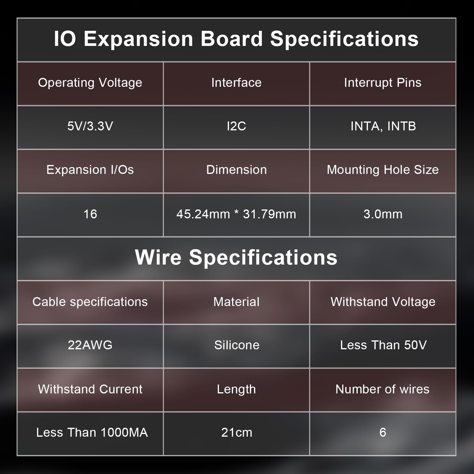
The CQRobot MCP23017 IO Expansion Board is a compact, I2C-controlled module that boosts your microcontroller’s I/O capacity from 2 to 16 pins. Compatible with major platforms like Raspberry Pi, Arduino, Micro:bit, and STM32, it supports up to 8 boards simultaneously for a total of 128 I/O pins. Featuring configurable I2C addressing and durable, eco-friendly wiring, it’s the perfect upgrade for complex, scalable projects.


| Brand | CQRobot |
| Package Dimensions | 7.11 x 5.21 x 1.7 cm; 32 g |
| Item model number | CQRMCP23017A |
| Manufacturer | CQRobot |
| Series | CQRMCP23017A |
| Graphics Card Interface | PCI Express |
| Number of HDMI Ports | 1 |
| Voltage | 5 Volts |
| Are Batteries Included | No |
| Item Weight | 32 g |
| Guaranteed software updates until | unknown |
C**J
Great for Raspberry Pi GPIO expansion
Awesome little board and well made! Used as a GPIO expander for a Raspberry Pi.So easy to use and wires stay attached to the pins.It worked so well that I went and purchased another.
M**S
Neat expansion board
The 23017 is a great little chip that allows you to add two 8 bit i/o ports to any microcontroller with I2C. This means that with only 4 wires (SDA/SCL and the 3V/GND power lines) you can have 16 individually programmable digital inputs or outputs that can be connected to switches or to relays, LEDs etc. This CQRobot board has two rows of header pins for the A and B 8-bit ports, also exposing Vcc and GND, so it's easy to wire up to other devices using Dupont leads. There is a red LED that shows when 3V power is on. The board also has an extension header that would allow you to add other I2C devices on to co-exist with the 23017.I connected mine up to a Raspberry Pi Zero W, and using the AdafruitMCP230xx Library for Python was able to set pins up to be inputs and outputs and connect a LED and a switch, for example, input:pin0 = mcp.get_pin(0)pin0.direction = digitalio.Direction.INPUTprint( pin0.value )or output:pin1 = mcp.get_pin(1)pin1.direction = digitalio.Direction.OUTPUTpin1.value = TrueThe microcontroller interface of the CQRobot board has six colour-coded silicon wires to connect to your Rasp Pi / Arduino etc, exposing the I2C bus, power and also interrupt lines for the A and B ports. The board design itself is a bit reminiscent of the Pi itself, with four mounting holes in the PCB and the same width as the Pi Zero (the length is about 2/3 that of the Zero).This is a great expansion board and easy to get working.
S**E
Seem good quality
Not sure if they work as I never got to try them - job was cancelled. But, seem good quality
P**H
time saver for prototyping
This product comes in a plastic case and all ready to go with all pins soldered up.It's a time saver in terms of hooking up multiple...ie lots of i2c devices to one controller, and uses a lot less pins than the normal way of just assigning different ports.You can change the i2c address if you want to by getting the soldering iron out and shorting tiny pins, but best if you don't have to as this is a bit of hassle.You can use existing libraries to interface with this but bear in mind you're going to have to have a basic understanding of arduino and i2c.
J**S
Excellent MCP23017 IO Expansion Board
This MCP23017 IO Expansion Board is really well made and very reasonably priced. The quality is excellent and it comes with the pinouts all fully soldered. The board has a detachable cable for easy breadboard connections.It comes neatly packed in a protective plastic box.Pure Quality! Great Price! Love it!HIGHLY RECOMMENDED! AAA+++
A**Y
Once you find their wiki this is just amazing
I have updated the review now that I have found the product wiki and all of the support code for Arduino. This is a board for expanding the amount of IOs that you can use on your Arduino or Raspberry Pi. It is compact. well made and easy to attach. The problems come in programming the functions for Arduino the support is excellent - I have not used it with a Raspberry Pi and so I cannot comment on that aspect. It isn't cheap but this reflects its compactness as most other expansion boards/shields are almost the same size as the Arduino board itself. This is idea if you need to build a compact piece of hardware but it comes at a price.
A**S
You will need to lookuo the wiki page. Awesome expansion board 16 extra IO pins
The concept is simple, 5V/3.3V power connection, Ground and a 2 pin I2C as the SCA and SCL signals and the other 2 pins and interrupt A and B lines.. with a connection in and out you can daisy chain up to 8 of these together and create a whopping 128 pins of IO - all you have to do is in 3-bit binary short the address onto the A0, A1 and A2 jumper link positions on the PCB (immediately next to the inlet connector) with all open circuit A0, A1 and A2 are all floating high hence the address of the expansion board is 0x27 - so with all three shorted it is 0x20 address, 0x21 is A0 open others shorted - key information you need to ensure you set this up correctly. This is a fantastic littke board and is very well made. Example software code is on the wiki page. Happy to highly recommend, Andrew
P**R
Good Build Quality - Poor instructions-Expensive
This item came well packed and build quality looks good.All inputs and outputs clearly marked on board as are the address pads.Unfortunately there was little to no information supplied with product, just a couple of references to webpages on packet label.A basic specification sheet was found after a search on the CQRobot webpage, as well as a link to a wiki page containing examples for use with both an Arduino and a Raspberry Pi.I cannot comment on Raspberry Pi example as I have never used one, but the example for the Arduino was extremely complicated and not very well explained (Poor English).The one code example given tried to incorporate everything the MPC23017 could do in one hit and for the average hobbyist (which is what Arduino's are aimed at) this was very difficult to understand.It would be more beneficial to have had simple separate examples of;Simply pulsing a pin on and offSimply reading a pins inputThen a full example of the more complicated interrupt routine, for those that wanted that feature.In summary, Good build but I do think it is a bit expensive, it does what it is made for but it is basically an MPC23017 chip mounted on a PCB.
ترست بايلوت
منذ أسبوعين
منذ شهر