We remain fully operational. Our teams are working around the clock to ensure your deliveries continue safely.

قم بتنزيل التطبيق


معلومات عنا
حقوق الطبع والنشر © 2024 Desertcart Holdings Limited
قم بتنزيل التطبيق

Buy anything from 5,000+ international stores. One checkout price. No surprise fees. Join 2M+ shoppers on Desertcart.
Desertcart purchases this item on your behalf and handles shipping, customs, and support to KUWAIT.
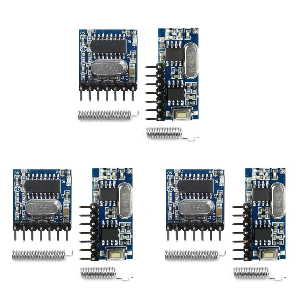
🔧 Unlock the Future of Remote Control!
The QIACHIP 3 Sets of 433MHz RF Transmitter and Receiver Module is a versatile wireless link kit designed for various applications, including home security and remote control systems. With multiple working modes and a wide voltage input range, this compact solution is perfect for tech-savvy users looking to enhance their automation experience.
| Manufacturer | QIACHIP |
| Item Weight | 0.634 ounces |
| Package Dimensions | 3.46 x 2.79 x 0.98 inches |
| Item model number | 369ecf7b-ccff-482b-a51d-d18fdf459a82 |
| Size | Small |
| Color | Blue |
| Style | RX480E+TX118SA 3SETS |
| Special Features | Android Auto |
| Batteries Included? | No |
| Batteries Required? | No |
R**W
Amazing Device
This is the second product I purchased from QIACHIP I am amazed at how well they work. I purchased the 433 Mhz version which also worked well see my review on that product. I noticed this 867 Mhz version which had some better spec's better receive sensitivity higher RF power output which increase the overall range of the unit. It also has a great feature that the board can be a transmitter or receiver by simply press the button on the board. It also will verify on the transmitter if the receiver received the signal by a short blink on the blue LED after the red one blinks. The range is fantastic on this board. I live on 5 acres and needed a device that could cover this size lot. I had no problem going to any part of the property and receiving the signal. I was running the test with the unit inside the house. If I mount it outside it will cover even more distance. I have been doing extensive testing of the unit and it works flawlessly. I tested all the board and they all worked with no problems. I plan on using them to extend fire alarms in my large outside buildings this will save me having to trench to run wires. I also want to put some intrusion detector around the property to let me know if anyone is on my property. I am very happy with my purchase and will continue to look at other devices they sell.
J**X
Go to qiachip web site for wiring diagram/paiaring instructions
Hard to tell if they were already paired since the 3 transmitters and 3 receivers came in one plastic bag. The qiachip web page has reasonable pairing instructions and wiring diagrams, but they are a little hard to find. The receiver diagram is overly complicated, all it really needs is power and optionally an led connected to a receiving channel pin. The transmitter needs power and a method of grounding a pin (channel) you want to transmit on. The transmitter and the receivers can be paired and tested without the antennas, at least at short distances. Both have red leds which will light up on pairing and transmission/receiving.
A**R
Difficult to get a reliable connection
I really wanted these to work but had stability issues which appeared to be antenna related. I could (with effort) get them to work without an antenna in very close range (like the supplier's video which also does not appear to have antennas connected). I could not get them to work at all with the supplied spring-like antennas. I tried an assortment of other antenna designs with varying results. The best I found was a simple 1/4 wave (~17.3cm) mono-pole wire antenna but there were still dead spots and sensitivities to surroundings that made them unusable for my application. It seemed like the matching pi network on the TX was not fully populated so maybe that was part of the issue and maybe with a network analyzer and more time I could have come up with a well matched antenna design for both but I'll save that for some time when I am bored. One of the 3 receivers did not work with any of the various antenna designs I tried so my guess is it was just DOA. While this would have been a useful design (i.e. no uC required), having spent way too much time trying to make them work reliably I decided to just go back to a simple "dumb" superheterodyne TX/RX + Nano with RadioHead library. That QUICKLY provided a robust/reliable connection with good range using similar spring antennas which fit my projects limited space requirements.
N**E
Inaccurate description, No documentation, existing libraries don't work
This is apparently some weird module to record codes from 433mhz remotes. I thought it was a plain old receiver and transmitter set. All you can find are weird videos on how to set up remotes with some weird unrelated receiver device. Nobody needs 'learning mode', i just wanted a transmitter/receiver. Go with tried and true, hiletgo . Completely useless in many ways. Disappointed I wasted my money on this trash
J**K
Good product
Works good
P**Y
Cool 4 Channel XMTR/RCVR Devices: A Bit Touchy To Set Up
As mentioned in another review, the pinouts don’t match up. Here is what I found:Pin Out Correlations:XMTR -> RCVR1 -> D22 -> D33 -> D14 -> D0VT: This pin goes high (VCC) when either a signal is received or when the red LED on the PCB turns on - it seems to be the same line. VT could be used as an interrupt signal to a MCU which then could determine which DO - D3 lines are active.MODE memory retention: Yes, the receivers retain the MODE setting between power cycles.Setting the MODE is a little tricky; basically you do the following:1) RESET the RCVR to clear the MODE and forget any XMTR IDs:Press the LEARNING button 8xExpect RCVR LED flash 7xWait 3 seconds2) Set the MODE:Press the LEARNING button 1 or 2 or 3 times depending on the mode you want to setWait 3 secondsExpect the RCVR LED to turn OFF (*1)3) Learn the XMTR ID:Press the LEARNING button 1xExpect RCVR LED to turn ONPress any button on a XMTR PCBExpect the RCVR LED to turn OFFNOTE(*1) These devices are very touchy about the timing of the LEARNING button presses. You’ll need to fiddle around with them to get them to work. Sometimes the RCVR will go into learn mode after a few seconds at the end of step 2 above (i.e the PCB LED turns ON) - if this happens just press any button on an XMTR. However, once the MODE is set the RCVR can learn or re-learn one or more XMTR ID codes.Issues:1. As shown in the picture, of the 6 pieces I received 1 of the RCVRS needed to have the flux removed. No big deal, but I suggest you keep and eye on this issue as contaminates can stick to flux.2. The pins on the XMTR PCBs are too short to work with a standard protoboard. As shown I needed to solder a pin header strip to extend them. If you are mounting these on a PCB this won’t be a problem.3. MODE setting is a bit touchyOverall, these are very nice well built little 4-Channel XMTR/RCVRs. Even with the above issues I’ll give it 4/5 stars because they seem stable once configured and, to me, they inspire some intriguing circuit applications.
M**M
Defective item
2 receiver module out of 3 were defective and did not work. I found out that the V+ and GND were showing 54 ohms while the one working showed 1.1 Mega Ohms. The modules that worked worked well
ترست بايلوت
منذ أسبوعين
منذ 3 أسابيع