We remain fully operational. Our teams are working around the clock to ensure your deliveries continue safely.

قم بتنزيل التطبيق


معلومات عنا
حقوق الطبع والنشر © 2024 Desertcart Holdings Limited
قم بتنزيل التطبيق
Buy anything from 5,000+ international stores. One checkout price. No surprise fees. Join 2M+ shoppers on Desertcart.
Desertcart purchases this item on your behalf and handles shipping, customs, and support to KUWAIT.
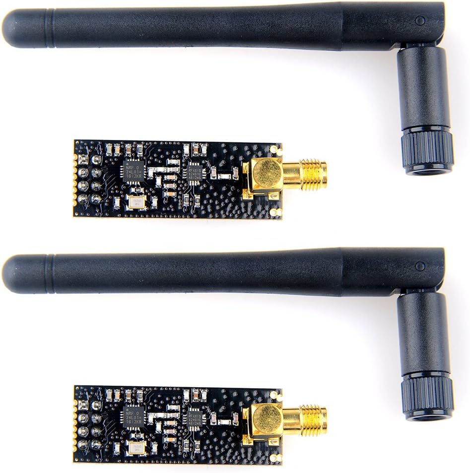
🚀 Elevate your IoT game with MakerFocus: wireless power and range that won’t quit!
The MakerFocus 2pcs nRF24L01+PA+LNA Wireless Transceiver Modules enhance the standard nRF24L01+ chip by integrating a power amplifier and low-noise amplifier, boosting transmission power to +22dBm and extending communication range beyond 1100 meters. Featuring an SMA antenna interface, low power consumption, and SPI compatibility, these modules are ideal for Arduino-based wireless projects requiring reliable, long-distance data transmission.
ترست بايلوت
منذ 3 أسابيع
منذ شهر
منذ شهرين
منذ 3 أسابيع