⚡ Command Your Smart Home Like a Pro
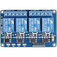
The 4 Channel DC 5V Relay Module by JBtek is a compact, PCB-mount relay board designed for professional-grade control of high-current devices up to 10A at 250V AC or 30V DC. Compatible with all major microcontrollers including Arduino and Raspberry Pi, it features four independent relays with LED indicators for real-time status monitoring, making it ideal for smart home automation, industrial PLC control, and advanced DIY electronics projects.
| Connector Type | Through Hole |
| Contact Material | Silver, Copper, Or Alloy |
| Contact Type | Form C Or Spdt |
| Current Rating | 10 Amps |
| Mounting Type | PCB Mount |
| Brand | JBtek |
| Operation Mode | Automatic |
| Coil Voltage | 5 Volts |
| Contact Current Rating | 10 Amps |
| Maximum Switching Current | 10 Amps |
| Minimum Switching Voltage | 5 Volts |
| Specification Met | Ma |
| UPC | 520361134553 |
| Item model number | 4450182 |
| Item Weight | 0.32 ounces |
| Product Dimensions | 2.56 x 1.97 x 0.79 inches |
| Item Dimensions LxWxH | 2.56 x 1.97 x 0.79 inches |
| Manufacturer | JBtek |
| ASIN | B00KTEN3TM |
| Is Discontinued By Manufacturer | No |
| Date First Available | June 6, 2014 |
M**T
This board + Raspberry Pi + good power supply = A great combination!
Excellent board for Raspberry Pi. Assuming you have a solid power supply, you can run this board off the +5v provided on the pin header (Pin #2). The relay board is fully buffered, meaning that the relay coils are not directly driven from the GPIO pins which protects the Pi and means that this board is plug and play. If you're going to be doing a lot of work with the RasPi, I highly recommend a USB voltmeter/ammeter combo so you can monitor your power usage. At full load, you want to ensure that your voltage on your USB port is as close to 5.0VDC as possible, anything less than 4.65VDC will cause problems with the Pi and stability. Your amperage should never exceed the USB power supply's capability. I use a 2A (2000mA) power supply and with full load (all relays on), the board + Raspberry Pi B+ only gets to .56A (560mA) so I'm well with spec. With all relays off, I pull about .24A (240mA)HOW TO HOOK IT UP:The board has a six pin header labeled GND, IN1, IN2, IN3, IN4, VCC and a two pin jumpered header labelled VCC/JD-VCC. Leave the jumper installed. For GND, you can connect to any of the GND pins on the Pi's header (Pins 6,9,14,20,25,30,34,39). For VCC, connect to pin 2 (+5V). Connect each of the IN pins to a GPIO pin (I used GPIO 8,9,10,11 which are pins 24,19,21,23 respectively).HOW TO CONTROL IT:Use Python (should be available in your RasPi distro) along with the RPI.GPIO library. You'll need to run your scripts with sudo as manipulating the GPIO pins requires root access. You can set the GPIO pin using GPIO.output(PIN, True) to turn off the relay, and GPIO.output(PIN, False) to turn it on. My only nitpick is that the logic is backwards. Driving a GPIO pin high (TRUE), should turn on the relay while driving the GPIO pin low (FALSE) should turn it off, but it's easily fixed in software.Pros: Plug and play, just works. Will be getting more of these. You don't have to worry about building interface circuits, transistors, load calculations down to the mA or anything overly complicated. Basic research into the GPIO library for Python, a couple of GPIO pinouts for the RasPi and I was up and running within minutes.Cons: Logic is backwards, you have to send a GPIO pin LOW to turn on the relay but this is a very minor thing and can be easily fixed in software.Verdict: If you are looking to be able to control equipment using a Raspberry Pi, this is the board to use.
A**R
LOTS OF MISINFORMATION EXISTS IN REVIEWS, PLEASE READ
Making the documentation myself:As there is no documentation, I was very skeptical of this unit trying to sink too much current to my RasPi's GPIO pins (which can only sink/source a max of 16mA per pin). Reading the datasheets for the individual components "confirmed" this believe by the Optocoupler (817C) showing normal operating current of 20mA - yikes!I crunched the numbers and took some readings from my relay module in use and found that the unit only sinks ~2.1mA on the IN'X' pins, well within the tolerance of the RasPi (most Arduinos can sink/source 40mA or so, so even less of a problem there). The reason why is there is a 1k ohm resistor in series with the optocoupler and an LED, so basically 2 LEDs and a 1k resistor (the input side of the Optocoupler is just an LED).Why did they make the optocoupler run at suboptimal current? It enables the relay to be de-energized when using 3.3V as is common on Arduino and is the only voltage the RasPi's GPIO can handle.READ HERE FOR HOW TO HOOK THIS BAD BOY UP THE RIGHT WAY (WITHOUT BLOWING UP YOUR PI OR ARDUINO):Arduino:Most Arduinos can handle I/O DC current of up to 40mA (This relay module only draws 2.1mA from the I/O pin). You probably won't encounter a microcontroller that cannot handle this current (if you do, that means you are probably an embedded engineer and this guide isn't for you). Some Arudinos can operate at 3.3V (not from USB), if this is your case then you will need a separate 5V circuit to power the relay module.RasPi:Raspberry Pi's are a bit more limited I/O wise than their Arduino brethren, only being able to take I/O DC current up to 16mA. Again, this is still well within the limits. We are using the Raspberry Pi's power bus, which the supported current is dependant on the USB powersupply you have chosen - if you are using a 2A charger like you should be, you won't encounter any issues.Relay Board:There are two rows of input pins (GND IN1 IN2 IN3 IN4 VCC) and (JD-VCC VCC) with the latter coming with a jumper bridging the pins (keep the jumper on!). Connect a wire from GND on your device to GND on the relay module. Connect a wire from the 5V pin on your micro to the VCC pin that is adjacent to IN4 (not the one next to JD-VCC!). Also note the 5V pin I mentioned is the actual 5V rail of the micro, not the GPIO or I/O pin that you are going to be using to trigger the relay. Finally hook the GPIO or digital I/O pin up to IN1 and set the pin to 'low' or 0V in the software to activate and 'high' or 3.3V-5V to deactivate.Special Considerations:If your board cannot source ~60mA from the 5V rail or if your board only runs at a maximum of 3.3V you have to use a secondary power source to power the relay.
C**V
Nice construction with clearly marked connections
With low side input voltage the board is great for 3.3 and 5V micro controllers or single board computers (e.g. Raspberry Pi). The board has been in service for a year without any problems (switching 2 to 8amps)
J**N
Actuates on low input
You need to know that it only takes a low input to actuate and that if you need to actuate using a high input aka high output from your source you should get a different one with options. Good board, just got burned because I didn’t do my research.
F**O
good item
Very Happy whit my purchase
S**Y
Work great, but note the 5V current draw
These work great with an Arduino. Just be aware that they draw enough 5V power that you can't reliably use more than one or two sets powered directly from the Arduino. With three I was causing the Arduino's internal voltage to drop, which caused random resets. The fix is simple - just provide 5V power to the pins on these modules from another source. Be sure that the ground is at the same level as the Arduino's, since the control pins use that as a reference.I soldered a thick wire on the underside to connect all 4 center pins. They are aligned so that you can do this without hitting other pins. That allows a single connection to provide output power (120VAC, for example) for all four relays in the set. Of course you must be careful that nothing conductive touches that live wire!
ترست بايلوت
منذ شهرين
منذ شهرين