


🔑 Unlock the Future of Convenience!
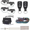
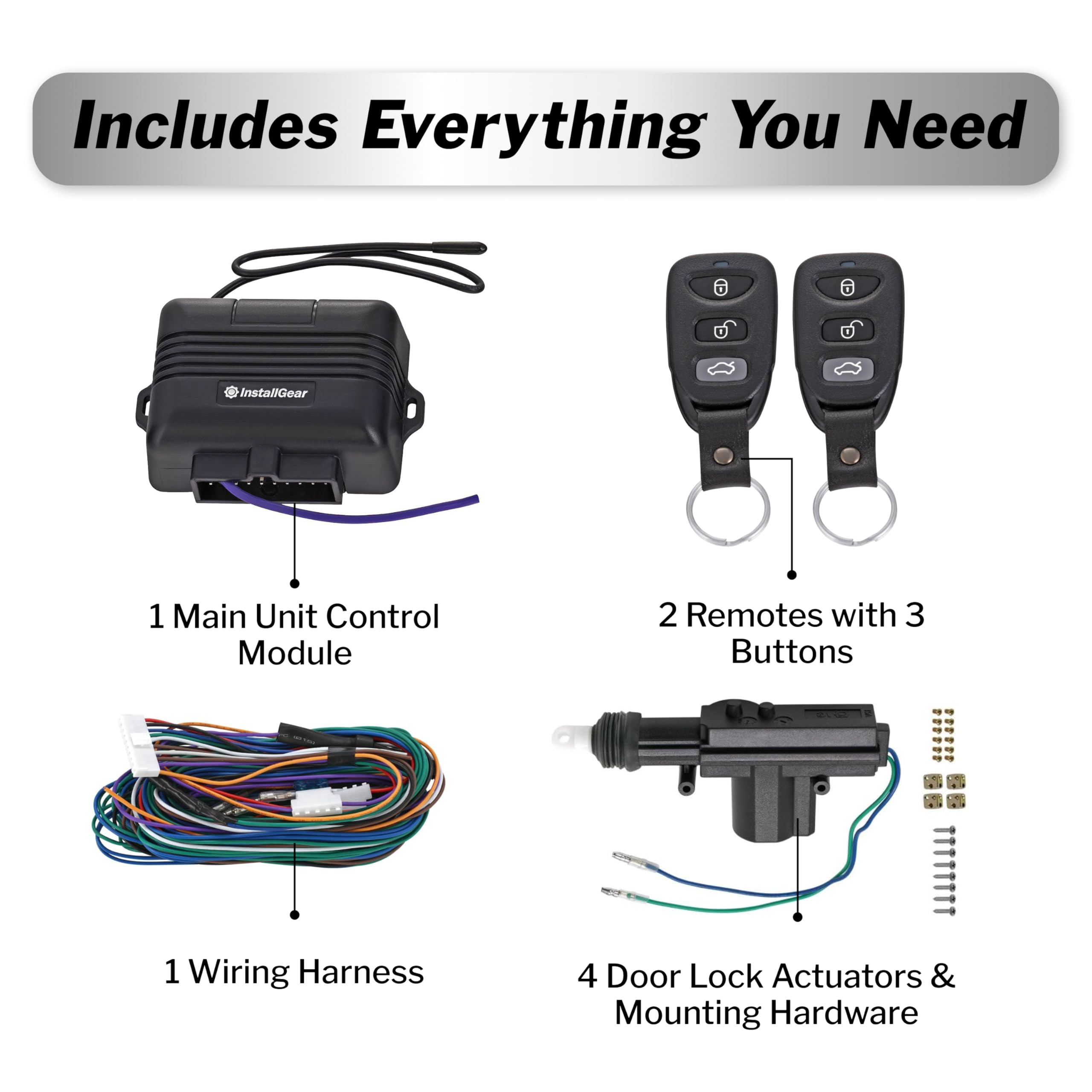
The InstallGear Keyless Entry System offers a modern solution for vehicle access with two 3-button remotes and four door actuators, ensuring compatibility with various vehicle types. This kit enhances security and convenience, featuring remote trunk release and visual confirmation for peace of mind.
| Manufacturer | InstallGear |
| Brand | InstallGear |
| Item Weight | 2.05 pounds |
| Package Dimensions | 11.34 x 7.52 x 2.48 inches |
| Item model number | IGCLS |
| Is Discontinued By Manufacturer | No |
| Manufacturer Part Number | IGCLS |
J**.
Working perfectly so far on 2000 Chevy Silverado
The media could not be loaded. Despite the lack of information in the instructions, I managed to get this system properly installed in a base model 2000 Chevy Silverado 1500 with a two-door cab. Since this is a two-door, I only used two of the four actuators. I hooked up a third actuator to a relay inside the pickup truck bed's toolbox. Then when I press the trunk-release button on the FOB, the relay activates the actuator and the lid is popped open. Since the release rod is ¼" diameter, I had to fabricate an adapter that would attach the thin actuator rod to the lid release rod. See photo.The wiring diagram is adequate for somebody familiar with such things. You can tell it’s been translated from another language as some of the terminology is not typical. There are no instructions whatsoever and you’re going to need some ingenuity and mechanical aptitude to get this installed and working properly.Out of the box, the inline fuses, diodes, and electrical connectors are included and already wired into the harness. This was unclear in the description so I already purchased an inline fuse.Note: This is a Master/Slave system. The Master actuator (5 wires) is mounted on the driver's door so when you manually lock/unlock using the factory manual door lock, the locking system is triggered and all other doors (the slaves with 2 wires each) will lock/unlock all passenger door(s) in sync with the driver's door.My recommendation is to setup a work surface near the front left fender so you can bench test the system between your driver’s side door and the battery. My battery just happens to be on the driver’s side. If yours is on the other side, then set yourself up near the opposite fender.Plug everything together as per the diagram and matching up the colors. Make sure to connect the 5-wire Master actuator and at least one 2-wire Slave actuator. Then you can temporarily hook up the red power lead to the battery using a clip. I pulled out the main fuse until it was hooked up and installed the main fuse last before testing anything. You can leave the purple (optional lights), orange (optional trunk), spare brown (optional switch), spare white (optional switch), and any spare blue and green wires disconnected. It should lock/unlock with the FOB and you’ll hear clicking inside the unit which would correspond to flashing the signal lights if/when those are hooked up. At this point, focus on the mechanical mounting while leaving the system connected on the bench. I mounted my first actuator in the door and plugged it into the blue and green wire connectors to test out the lock/unlock operation before I committed myself and permanently routed the harness throughout the truck.By default, LOCKed is when actuator fully RETRACTED. If you cannot physically mount the actuator in the correct orientation to make this happen, the system is fully reversible as I will explain below. Mount the actuator in the orientation that makes the most sense mechanically/physically, and then you can reverse certain wires as described below that will flip the operation of the system while maintaining the proper operation of the designated lock/unlock buttons on the FOB. In all cases the polarity to cause retraction is blue (-) and green (+), and to cause extension is blue (+) and green (-).Let’s go through this wire by wire as per their included diagram:RED (with inline fuse) - 12 volt DC CONSTANT power from your battery or fuse box. The diagram shows a 10-Amp inline fuse, but the wiring harness includes a 15-Amp inline fuse. I think these wires are too small for 15 Amps so just to be safer, I downgraded my inline fuses to 10-Amp. Since I’m only using half the actuators, I’ll be using half the power and therefore 10-Amp protection should be more than plenty. Worst case, you can just use the 15-Amp fuse they supply with the system. I ran one 14-gauge red wire from a spare fused 12-volt threaded post in my engine compartment's fuse box and then through the firewall boot to under my dashboard. My truck supplies these spare fused 12-volt posts in my fuse box, but you could use a fuse tap device or splice into your power someplace else. Just make sure it’s done safely and correctly as you don’t want a short circuit causing an electrical fire. You may be able to find a constant 12-volt wire under your dash, but it was safer and easier for me to find it under the hood.BLACK (with RING connector) - This is negative power from your battery, which is also connected to vehicle ground. The included harness already has a ring stud connected to this black wire so find a metal stud or put a screw through a hole in any grounded metal under your dashboard and connect this wire here. Make sure the metal is clean and connected to electrical ground. Ground can be verified with a continuity test or a meter. Consult with an electrician if you’re unsure.BLUE and GREEN (with connectors) - These pairs of wires connect to each actuator and carry the power that causes them to push out or pull in. By default, LOCK means the actuator is RETRACTED. If you need to make the actuator UNLOCK when RETRACTED, then you need to REVERSE the Blue and Green connections at EVERY actuator or the system will not operate in sequence. If you don't use all four actuators, it's perfectly safe to clip off the extra pairs of Blue & Green wires. Just be sure to individually tape the ends as these will be energized when locking/unlocking. Bare Blue and Green cannot touch each other or the system will short out.BLACK, WHITE and BROWN (with connectors) - These wires get plugged into the MASTER actuator only. Black is the "common" or system ground. White and Brown tell the system the position of the actuator. By default, the actuator is in LOCK position when RETRACTED. If you need to reverse this operation, then you’ve already reversed the Blue & Green wires as described above. IF the Blue/Green actuator wires have been reversed, then you MUST also reverse the White & Brown wires at only this connection to the Master actuator. Black stays Black (ground).WHITE and BROWN (extra wires) - These wires are for the OPTIONAL switches. If you want to hook up a lock/unlock switch then use these spare wires for that. Switch should be a “momentary contact” or you will apply constant power to the controller and probably burn it out. Connect a switch between Brown & ground (Black) and you will UNLOCK the system. Connect a switch between White & ground (Black) and you will LOCK the system. Even if you reverse the actuator operation as per previous paragraphs, Brown is ALWAYS UNLOCK and White is ALWAYS LOCK… these optional over-rides never get reversed and always correspond to the Lock/Unlock icons on the FOB.VIOLET (purple with diodes and inline fuse) - This purple wire pulses your signaling lights when you lock/unlock via the FOB. One flash when you lock, and two flashes when you unlock. If the car has already been locked, you will see 5 flashes when pressing lock icon. You can hook this up to parking lights (NOT headlights), turn signals, or another 12-volt lamp. The diodes protect this system from back-feeding power when you use the lights normally. I selected turn signal lights because these are the brightest. Also, I have remote start that turns on the parking lights, so I use the turn signal lights to differentiate this lock/unlock FOB. They give you two diodes and two purple wires precisely for hooking up to each of the two turn signal wires. These can be tricky to find so be sure to consult with your vehicle’s wiring diagram. Since I downgraded my main 15-Amp fuse to 10-Amp, I also downgraded this fuse to 10-Amp. It makes no sense to have this signal light fuse larger than the main fuse as it would never protect anything and all power still goes through main fuse on red wire. If you draw too much power and blow fuses, then go back to the 15-Amp they provide. Otherwise, you probably have a wiring problem or bare wire touching ground someplace.AMBER (extra wire) - (Actually, this wire has an orange color.) This is for a trunk release actuator. The diagram shows -300 mA. So this one seems to be causing the most confusion and complaints in these reviews. In order to see the 12 volts from this output, you measure between +12 volts (red wire) and this orange wire. Then press the trunk icon on the FOB. It is a brief pulse no matter how long you hold the button. 300 mA is not a lot of current, so if you hook up an actuator directly to this orange wire, you will likely draw a lot more than 300 mA and burn out the controller unit. My recommendation is to hook up a small automotive style 12-volt relay to control your trunk actuator. Without getting too far into the wiring, the COIL on the relay would get +12 volts on one side and this orange wire on the other side; and the coil only draws ~ 100 - 150 mA. Pressing the FOB trunk button will activate this relay. Then you can use the switch side of the relay to control an actuator and/or any other accessory.https://www.amazon.com/dp/B072QXDZRD/ref=cm_sw_em_r_mt_dp_U_fY0WCbYSKAGKHMechanicals: This is entirely up to you and your mechanical skills, but you might have to make brackets and cut & bend the control rod. It’s critical that the actuator pulls its rod as straight and parallel to the normal operation of your OEM rod. I’d also make sure the rubber boot does not rub on anything. Roll down the windows to make sure the actuators and wires stay clear! See my photos and video.Routing of wires is up to you, but my truck had rubber boots in the door jambs for speaker wires. I removed my plastic panels to get to these boots on both sides to release it. Once the boots were loose, it was easy to push all the new wires through. Then snap the boots back into place and lock wires are hidden away with the speaker wires. I was also careful to tie all wires to existing wiring making sure there was no place that would rub the wires and short them out. I also purchased 100 feet of ⅜" split loom for protecting the wires.https://www.amazon.com/dp/B00J7RD6ZI/ref=cm_sw_em_r_mt_dp_U_eV0WCbRTGT18MSince the master actuator contains switches that control the other actuators, you may have to fuss with this rod the most. It’s critical that the amount of travel of your factory lock lever be within the same amount of travel to trip the internal switches of the master actuator. On my first attempt, after putting my door back together, I no longer had enough travel on the lever to engage the master/slave function on the unlock side of the lever. I had to loosen and adjust the new rod length a slight amount towards lock position so that the plastic lever pushed the rod enough in both directions and it’s working great now.Documentation quirks:It shows the spare White/Brown wires with text, "Connect with Main Unit" - very misleading. Read my explanation above. These would connect to ground through an OPTIONAL momentary switch. Brown to Black (ground) triggers UNLOCK and White to Black (ground) triggers LOCK.The wiring diagram shows "Parking Lights" with two wires and a "left" and "right" lamp. However, these are really the turn signals. If you tie into the parking lights, you only need one purple wire. If you tie into the turn signal lights, then you'll need both purple wires.Under “Operation Instructions”:“Lock - Press once to lock the system (hold for 20 seconds (-) output will engage for window roll-up)” ~ I have no idea what they’re talking about as there nothing in this system for windows; no extra outputs, wires, etc. And nothing happens when you hold this button for 20 seconds. Press this button, the signal lights flash ONCE and the doors simultaneously lock. If the car has already been locked, and if you try to lock it again, the signal lights will flash FIVE (5) times."Unlock" ~ Press this button, the signal lights flash TWICE and the doors simultaneously unlock. They fail to mention that holding THIS button for 2-½ seconds will subsequently send the trunk release signal. There are no signal lights with trunk release.“Trunk Release - Hold for 2-½ seconds , lights will flash three times and trunk will release” ~ There is absolutely no 2.5-second delay on the trunk release button and the signal lights absolutely do not flash as part of the trunk release operation. Press trunk icon on FOB and you'll IMMEDIATELY get a pulse of 12 volts between the red and orange wires.NOTE: The trunk release circuit is limited to 300 mA so it's safest to only hook up a relay coil and use the relay contacts to apply voltage to any actuators. Otherwise, the actuator might draw more than 300 mA and could burn out the electronics. Again, if you don't understand how to hook-up a relay, please consult with an expert.2023 EDIT: It's been nearly 4 years since I installed this system and it's still working great without any issues.
M**O
Works brilliant (NA MIATA 94)
Installed on a NA Miata (MX5) 1994.Item is as effective as published, instructions are kind of simple, specially for the trunk open function. For this, I was good on # of actuators as the Miata only have 2 doors, but need to read a coupld of awesome reviews here that explain how to wire the actuator with a 12v relay.Everything works as expected!! Superb practicality for the price!
D**A
Pretty good overall
Installed on a E150 van; all wire connection colors match. I have power locks now but... The wire harness and or control unit is wired wrong: lock/unlock are backwards (not a big deal, just connect the blues to the green control & vice versa) and the white&brown wires don't work, as soon as you connect them they send a lock signal to the main actuator, pushing unlock works but immediately returns to locked. they are useless anyway as all the locks work together without these connected; if they have a purpose there are no instructions. I don't understand the trunk pop, its says -300mA and shows connected to red on diagram, it sends a one volt signal. I found on the net that it can be hooked to pin 86 as a negative for a relay but why? it should just send 12 volts. The blue&red wires are a giant mess and a fight; I just cut them and reconnected after they were run. I had to add wire to reach the back door. the short white&brown wires are for a switch; brown locks. I don't want my lights to flash so purple wires are unused but it will still make clicking sounds; they worked when bench-tested using LEDs. For an E150 this was easy to install, but time consuming, about 5 hours by myself, easily less with any related experience. I did have to drill holes to mount the actuators and luckily I didn't need to use the bendable brackets or bend the bars; there was a convenient place to mount them for good linear motion. make sure you don't interfere with the windows. The remote works from a very long way away. There is a server error when trying to email support; I did not try to call, so with that, the trunk pop, and the white/brown wire issue, minus two stars but I will add one back because this system does work. I like it
Trustpilot
2 months ago
1 month ago